Just like most of everybody else who builds a photo booth, I am making mine for a wedding… and just like them, it’s for my own wedding. I was planning on putting the booth into my game room after the wedding and using it with friends during parties and what-not… Apparently photo booths are also the latest craze in weddings right now, so I decided to make it good enough to rent to others to enjoy at their events. Below, you can see how I started, and ended up building my booth, which has now been named the Best Shot Photobooth.
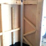
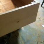
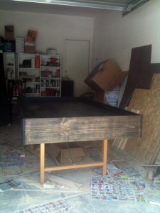
Let’s skip ahead into the build by a couple weeks. Here you will see the basic structure of the booth, which is plywood put around a 2×4 frame. The front face has been routed out with beveled edges to give smooth, rounded corners for the camera, lights, and computer monitor.

I haven’t been following anybody else’s design or layout, but instead just going off of what I think of when I picture a classic photo booth.

The component part is big. It’s big on purpose. Why? Because that’s what the older photo booths looked like. They had to have all that photo processing equipment in them. I wanted my booth to resemble what I’ve grown up to know as a photo booth. My design isn’t the most space efficient, but I’d rather have it this way than a skinny kiosk-type booth. Dont get me wrong, those are just fine, but I want this in my house at some point, so I get the final say on the design 🙂
The entire booth comes in 4 pieces. The computer component side, the seat, and the roof + floor. The floor latches from the insides to the other 2 components and the roof gets bolted down with wing nuts. This is what makes the entire setup portable. Granted, it’s made out of wood, and therefor pretty heavy… but it’s still easily managed with a dolly.
Anyways, I decided to stain the entire booth a nice mahogany color.
Unfortunately, I was finding it difficult to get a good color scheme figured out. Black kind of worked, but it’s a bit boring. The gray and silver below didn’t work at all, but I was more or less just testing with what paints I had in my garage at the time.
I had made a simple cardboard prototype of what I thought the button console should look like. I was absolutely positive that I wanted the button on a console, instead of just mounted on the front face of the booth. IMHO, it just looks way better than a flat button.
Also, I was considering the future of the booth as well. Later down the road, I may end up putting a keyboard and/or more buttons on it for various other features (Social network uploading, etc)… but for MY wedding, I just wanted it to have one single button — easier on the grandparents that way 🙂
The button itself will be a giant red light-up button, ordered from Sparkfun for around $10
This is the seat half of the booth. You can see blue masking tape marking where I thought was the best placement for buttons. Figured the ‘dice’ pattern was better than the inverse of that (top row 1 button, next row 2 buttons, next row 1, etc etc)
We started the upholstering with some carpet padding. It was WAY cheaper than upholstery stuffing/padding. Like, in the 10x magnitudes.
Once we got all 3 pieces covered, I had to put the buttons on. This involved drilling a hole, and using some really strong upholstery thread and a huge needle. (This is the first time I’ve ever attempted upholstering anything by the way… I’m just lucky I had help)
To pull the buttons tight, we first just stapled down the thread on the back of the board… but I figured there had to be a better way…
I then figured out a way to make them adjustable… just add zip-ties 🙂
I tied the thread to the zip ties, then stapled down the ties. I could then tighten the buttons to exactly how tight I needed them to pull from the front.
IMHO, the buttons came out pretty nice. I had originally pictured, and would have preferred a more “poofy” look, but you can only get so much out of carpet padding, lol.
If you can’t tell from the above pics, the seat part is actually a lid to the storage area below. I wanted a storage area to put whatever, but mainly for a box of props that I’m sure will always be with the booth.
As for the other half of the booth, I did some work on the light boxes. For one thing, I painted them white (to reflect as much light outward as possible. I only did one coat, since it didn’t need to look pretty, but more importantly, not be brown.
After that dried, I then started preparing the plastic panels to be put in/on the cutouts. I used my drill press (my second favorite tool in my garage, lol) with a countersink bit on it to get some nice holes for the tiny screws.
Unfortunately, the plastic wasnt really agreeing with the amount of heat any of my bits were making 😛
My regular drill bit really got mucked up.
Here’s the front half of the booth with the 4 plastic panels installed. Two are white diffusers (for the lights), one is completely clear (for the camera), and the other is smoked (for the monitor)
Here you can see the panels installed, as well as one of the two shop lights for the light boxes. On the other box, you can see all the light leaks that had to fix using various methods.
I only had 2 of the 4 bulbs, but you can guess what both lights will look like by seeing one of them turned on:
Here are the cutouts for what would soon be the control panel. A larger board would sit on the top of this box (the board underneath is not part of this)… on it will be one lone red button (seen above), which will start the photo process.
I decided to glue the box together, instead of nailing it. I built it in a way that would let me mount it to the booth while always keeping pressure on the right part of the console so it always pulls itself together… in other words, it will always be clamped. Nails or screws would be overkill here.
After the glue had dried on the box, I then started thinking of a way I was going to be able to attach the console to the booth…. I figured I could just use some straight bolts, that way I could take it off whenever I needed.
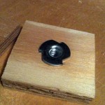
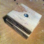
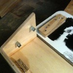
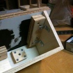
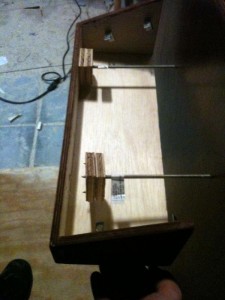
I then created the mounts for the bolts to attach to. Hopefully these pics explain what I did here…
I put the mounts on the back of the front piece of the box, since keeping pressure on this will help keep the sides and bottom of the box tight.
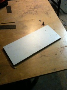
As for the top of the console, I cut this out from pressed wood / melamine.
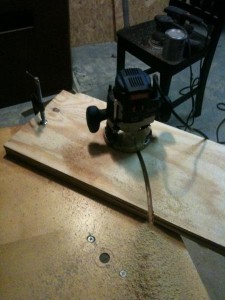
I was a little hesitant of making the round corners on it, since I would have to do it by hand with the router…. but after mounting the router upside down and manipulating the piece itself instead of the router, I found out it was easier to control than I was expecting, so I just finished off both rounded edges.
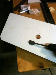
I also put in the central hole for the button that would be on the console. I plan on putting in more buttons for various things later down the road, but for now, the one button is all I need.
When I tried to mount the button in the hole…
…I noticed I had a problem.
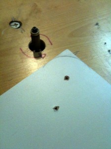
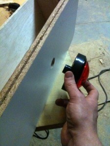
The button mount was shorter than the wood was thick. It didn’t reach. It scared me at first, but a second later, I realized I had my router right behind me, haha… so I cut a recess on the back of the panel.
That solved that problem. I was able to attach the large nut onto the button post now.
After the button was taken care of, I just needed to mount the top of the botton console to the rest of the box. I decided that I should do it the same way that I did the box bolt mounts, that way I can easily take it apart to be able to alter it later.
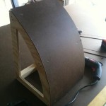
For comparison, here’s the unpainted console sitting next to the early cardboard prototype I built. As you can see, the design changed completely, haha.
Front view of the console, while sitting on top of a speaker.
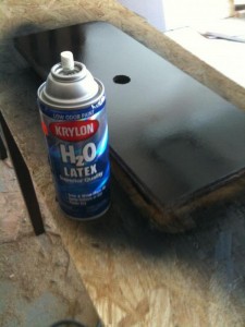
That latex paint from Krylon is probably the coolest paint Ive ever used, haha. It will paint over things that most other paints wont. I was even able to paint onto styrofoam, whereas most other paints would just melt the styrofoam away. I used it on the melamine surface for the console, and am very glad I did.
I put 3 coats on it, since this part will be getting handled the most by people’s hands and whatnot. I first encountered this stuff on the console of an arcade game cabinet. I was trying to strip it off, and was impressed at how thick it was and difficult it was to scratch off, so I decided to research and find out what it was 🙂
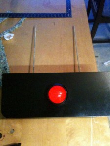
This is what the console looks like after being painted and stained (I still had to put on polyurethane and the T-Molding)
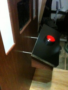
All that was left to do now was attach it to the booth. To do so, I used some long bolts and screwed them into the bolt blocks I made earlier. This left me with 2 bolts sticking out of the console.
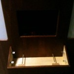
I then drilled 2 holes in the front of the booth, below the monitor. The bolts of the console go through them to the inside.
The bolts come into the bottom half of the cabinet. They pass through a 2×4 on the way in. At first i was a little skeptical about using the 2×4 as support, but I later decided that it would probably help the leverage of the console from the inside, especially if somebody decided to put some extra weight on the console.
I put some oversized washers and some wing-nuts onto the bolts and started tightening it down from the inside…
While i was tightening it down, I started hearing that telltale sound of wood splitting. I immediately loosened the nuts and went around to check out what was going on with the console. Apparently, it seemed that the bolt blocks weren’t attached to the box very well. I was able to easily pull it off, which revealed that the screws had barely gone through the wood to the box.
Easy to fix, but that could have caused some serious problems later if I hadn’t discovered it.
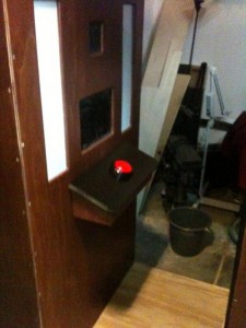
After I had driven the screws in deeper, I tightened the bolts again, and everything seemed to be good. I figured I would have to add a small piece of wood to the outside-bottom of the console, because at this point it tended to slide around a little, even when tightened (as I expected it would).
Ok, let’s talk about the inside… specifically, how we will get the printed image to the user. What seems to be the industry standard in photo booth building, is to spend a lot of money on a high end photo printer… well I can tell you right now that that was way out of my league, so I could only splurge a little on the printer itself.
I went out and bought a Kodak 5250, which is apparently really good at photos for a sub $100 printer, according to reviews and recommendations.
Now that I had the printer, I had some basic dimensions to start building a mount for it.
I decided to hang it from the top of the cabinet, since that would give the most freedom of designing a way for the printed pics to fall into the paper holder (on the booth).
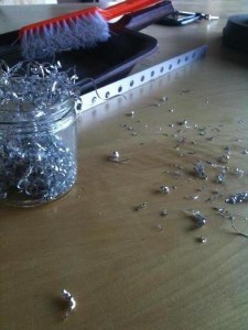
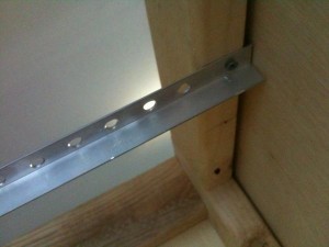
Using my drill press, I created some simple rails with mounting holes out of stock aluminum angle.
I then put in some long bolts, and a flat wooden platform. Using this configuration lets me adjust the platform, the base, and the angle of pretty much everything about the printer mount – that way if this printer craps out on me, I wont have too much trouble putting in a new one 🙂
This got me as far as hanging the printer itself… I still had to figure out a way to let the actual photo printout make it’s way to the outlet. This was a little trickier than I had thought. Mainly because I was having a hard time finding the right material that would curve and also be slick enough to keep the photos from getting caught on it.
I’ll keep from boring you about all the different ideas I had on this part (one idea even included using a trash bag – oi)… and just skip to what I decided on using. Basically I had to build my own ramp.
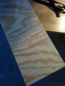
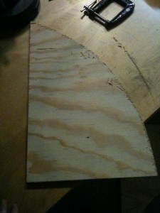
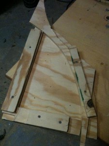
I first used a bent piece of wood to get a generic curve drawn onto some plywood, which I then used a jigsaw to cut out. This gave me one rough cut piece
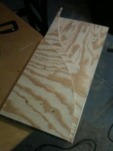
After sanding and smoothing that rough-cut, I then used it as a template, as well as a few other quick techniques to get more curved pieces as well as hollow them out
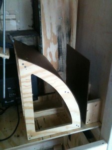
After getting 3 good pieces to use, I then just took some 2×2’s and put them all together
Then I measured to make sure the ramp was the right shape and size… which it was 🙂
That’s when I put on the thin board that was both pliable and slick. I really don’t know what it was called, as I didn’t even read the label when I picked it up at the Depot… I just saw it and figured it would work 😛
After finishing the ramp, I thought I did a good job on it and let it be. Then something hit me like a sack of bricks… when I measured the ramp for its fit, I forgot about the giant CRT monitor! So I went and got the little monitor that I was going to use, I put it in place, then I put the ramp in place.
Sure enough, the ramp no longer fit in its spot. Guh. I knew I forgot something.
Ok, so for about 20 minutes I went over my options on what I could do… they ranged from rebuilding the ramp, to dismantling the CRT case, to actually giving in, and ditching the CRT and using a new LCD screen instead.
Then I just decided to do it the more archaic way…
😀
It may be lazy, and it may be messy, but hey… it works!
After I made sure it all fit once again, I had to make one more simple back-stop guide for the photo path, and then I was done. Photos were falling right where I wanted them to 😛
Now let’s go back to how I (re) mounted the button console.
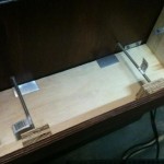
What I did was use some cheap aluminum angle and cut pieces about 2 inches each, then mount them alternatingly right where the bottom of the console goes. What this achieved, was that it was now basically gripping the box, holding it there and keeping it from sliding around, like it was before I had the supports on.
You can see the metal tabs from underneath the console, which I really didn’t want showing at all, but in most cases, nobody is going to bend down and inspect it anyways… and those who do will see just that; 2 metal tabs. They don’t look bad at all.
As for the console itself, myT-molding finally came in the mail, and I put it on. My makeshift rubber mallet worked pretty awesomely 😛
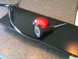
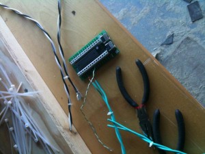
After pretty much deciding that the console was finished, I then wired up the 4 wires needed for the button – 2 for 12v, and 2 for the button switch itself. I ran the 12v wires to an old wall-wart transformer I had lying around, and I ran the switch to the space-bar input of a spare iPac controller I had lying around in my arcade cabinet parts drawer. The iPac is basically a keyboard controller that breaks out the keys to terminals for you to wire to anything. It is way overkill in my case, since Im only using one button, but hey, it works and I wasn’t using it for anything else 🙂
If I were need another one, I would probably go with a Teensy this time around. Much cheaper, while following the same concept.
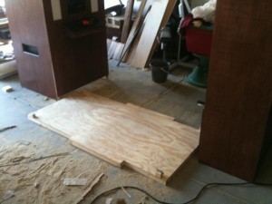
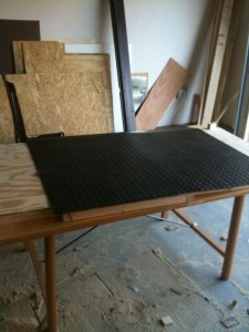
As for the bottom of the booth, which had been neglected for many weeks now, my special ordered rubber coin-mat had finally arrived, so I set out to finish the flooring.
As mentioned earlier, the 3 pieces (4 if you count the roof) slide apart for easy relocation. This made the floor relatively easy to work with, as opposed to the rest of the parts.
Measuring and cutting the rubber flooring was easy enough… a regular pair of scissors got that job done… Some industrial adhesive kept it stuck to the wood pretty nicely.
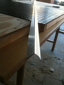
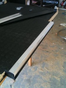
Using the same aluminum angle that I had used on the console box (a carpet-edge transition bar), I measured and cut two lengths for the sides of the floor where the user is to step into. A hacksaw takes care of aluminum perfectly.
With the supplied finishing nails, getting the bar on was easy enough… and it looked pretty good to boot 🙂
At this point, it is all minor cosmetic work now. I had chosen my software for the booth also. At first, I had planned on writing my own. While it could be done, there were two reasons why I chose not to. Reason 1: I was running out of time very quickly. I had about 1 month left before this needed to be done, and I was only able to put in my time after work every day. Reason 2: Somebody already did it, and they did an amazing job at it! While researching my options, I came across Sparkbooth. It is an amazing piece of software, written by the talented John Wu. Not only did he have the perfect piece of software for me, but ever since I had bout it in early 2011, I have noticed many updates, increasing the functionality of the booth every time. It will no longer take much effort to be able to get photo pics onto the social networks, or let users get their pictures emailed to them. It’s all built into Sparkbooth!
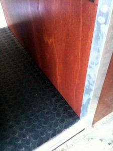
I thought the black/silver/red all complemented eachother nicely. Much better than I had anticipated. Here is a shot after finishing the floor and putting the pieces together, along with some aluminum angled pieces I had found at my local metal shop – I put one on each corner.
Another thing that had happened was that we found out my awesome black background wasn’t going to work. It made every photo come out blown-out, screwing up the white balance of everything. Most photographers know exactly what I’m talking about. Black backgrounds are a tricky thing to work with.
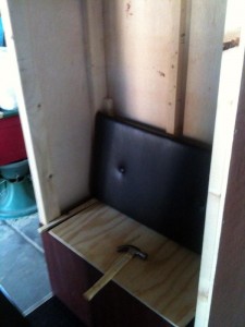
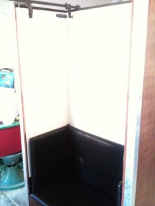
Since the full-black background wasn’t going to work, I had to think of some other way to do the background. I didn’t totally want to ditch the leather, but I couldn’t use it as the background. So I did the next best thing – I just kept it as the back rest, and followed it around to the sides.
I decided to put white as the backdrop for now. I set out to find a suitable material that wasn’t going to cost an arm and a leg. Luckily, I found the perfect stuff at the Depot. It is a large sheet of PVC, made for showers and other places needing waterproof materials. One sheet of the stuff was perfect, but alas, I screwed up a cut and had to go buy another sheet anyways.
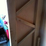
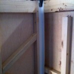
Before I could put the material up, I had to put in supports on the sides and back… It admittedly just added more and more weight, something Ive been trying to avoid the entire time, but without it, the PVC sheet would simply bend in and possibly break off.
As seen above, pushing up 2 cut pieces of PVC would usually show the dark area at the seam, so instead of continually trying to perfect beveled cut, I just put a bent piece of more PVC between the joins.
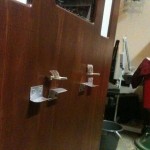
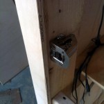
I also had to figure out a way to attach all the padded boards to the inside… this step was a lot harder than it seems like it would be. I was looking for a way to attach the boards without having to put a hole in the leather OR put a hole in the outside of the booth.
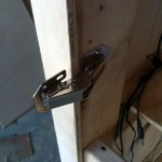
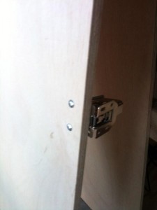
I settled on using a medium that I’m not quite happy with, but got the job done. The image is a little blurry, but those are actually just cabinet door catches.
After securing the pads, and hanging the PVC, it was starting to look like a booth again
I put on some more aluminum siding to cover the PVC ends, and the bare wood edges next to the seat, and since I don’t have a direct picture of it, your going to have to trust me when I say it looked pretty nice on that black leather.
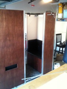
Next I had to put doors on the back. Simple stuff here. Just had to buy the right hinges and put on some regular plywood paneling, then stain to match.
This is the only place on the entire booth where you can see bolts from the outside. I just couldn’t escape it here.
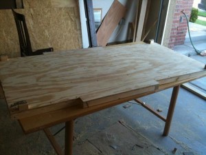
After that was all done, I was ready to complete the booth by building the final piece: the roof.
From the very beginning, Ive been trying to think of how I wanted the top to look. I wanted it to jut out a little, drop down, and give height all at the same time.
The actual building of the top was relatively easy… it was just an open-topped box, with the bottom raised in a few inches.
I thought it would be best to use black as the color, to complete the accenting colors. This pic is only one coat, but you get the idea.
To be perfectly honest, I’m not sure I’m totally happy with the top. Something just looks… “off” to me. I’m not really sure what I could do differently. Got any ideas?
All in all, the build was really fun, and the results were awesome. At our wedding, there was a line to get into the booth all night long. It was a total success.
(the back door is open in this first pic)

























Great Job!!! Love the detailed story, and all the pictures…didn’t know you were taking them step by step. Just AWESOME!!
Wow….. impressive….Great job.
Bill commented on Now Hear This:
Wow….. impressive….Great job.
Ginny Ragans commented on Now Hear This:
Great Job!!! Love the detailed story, and all the pictures…didn’t know you were taking them step by step. Just AWESOME!!
Hi,
How much did all of this cost you roughly?
Thanks
Connor commented on Now Hear This:
Hi,
How much did all of this cost you roughly?
Thanks
I am so excited to be able to have this at our upcoming wedding! I had the chance of being able to see and use the photobooth at Brian’s wedding. Its wonderful!!
What kind of software did you use?
I actually had not used any software whatsoever for this design… I most definitely should have, though. It would have saved me a bunch of time and mistakes.
If I were to make another one today, I would design it in Google Sketchup.
Mason commented on Now Hear This:
What kind of software did you use?
I actually had not used any software whatsoever for this design… I most definitely should have, though. It would have saved me a bunch of time and mistakes.
If I were to make another one today, I would design it in Google Sketchup.
Will anything posted here really post as Brain to facebook automatically? or did he just copy/paste it?
You should know me better than that 😛
Feature tester commented on Now Hear This:
Will anything posted here really post as Brain to facebook automatically? or did he just copy/paste it?
You should know me better than that 😛
it worked!
It also works the other way as well. Comments get synced every 10 mins
I’m on it!
oh, actually, the scripts only pull comments FROM facebook if the original post is less than a week old…. soooo…. its not gonna work right here, heh
DANG. So where is it now? Sitting collecting dust?
If you still have it, I imagine it is very heavy, but would you consider renting it out?
This was very impressive work. Great detail, step by step, and awesome pictures. My friend went ahead and built a perfect booth with your instructions.
He is realizing it’s very difficult to move and transport. It’s extremely heavy. Any suggestions? Can he use another material?
Thanks again.
Amazing! I have to build an 80s customized booth for an event. How much did you spend on this?
Thank you
I would suggest using Darkroom as your software
Its easy to make custom templates and to program your session
I wish you made a portable booth like this for sale I would be interested in the shell
Use a subdye printer and your set
You should consider makeing a selling these
I would pay a good 9500.00 for it
CARBON FIBRE PHOTOBOOTH. Or fiberglass… I guess. No more eighties vibe tho.